Software Library for structural analysis of 3D Frames and Shells with the Finite Element Method
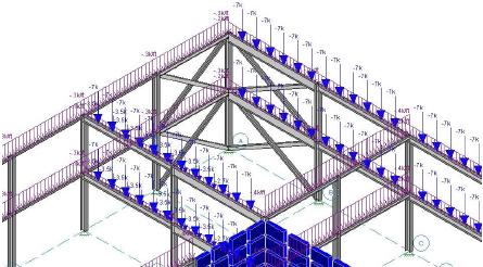
3D Frame Analysis Library performs advanced linear and non-linear analysis of structures in 3D space (frames and shells) and calculates all internal forces (axial, shear force diagrams, bending moment diagrams), displacements, rotations, support reactions etc. The software library can be directly used from Visual Studio, so that the structural analysis can take place immediately without the need of intermediate files.
Static, Dynamic, Linear & Non Linear, 3D Structural Analysis. The ultimate object-oriented finite element library. One time fee. Royalty-free!
Now more powerful than ever with optimized methods that dramatically decrease solution time
3D Frame Analysis Library performs advanced linear and non-linear analysis of structures in 3D space and calculates all internal forces (axial, shear force diagrams, bending moment diagrams, shell element stresses/forces), displacements, rotations, support reactions etc. The software library can be directly used from Visual Studio, so that the structural analysis can take place immediately without the need of intermediate files. Supported analysis types include linear and non linear structural analysis under static or dynamic loads, while Modal and Response Spectrum analyses can also be carried out effectively. The developer can use any .NET compliant language, such as C# or VB .NET, specify the input parameters (geometry, materials, cross sections etc.) and finally obtain the results of the finite element analysis.
The 3D Frame Analysis Library is a complete analysis library for solving structural problems utilizing a powerful and robust analysis engine, which in combination with the reach analysis and element features can efficiently solve large scale static, dynamic, linear and non-linear problems. It has been developed from scratch by ENGISSOL Ltd.’s Research & Development Department using the reliable and accurate platform Microsoft .NET and following the principle of object-based programming, a fact that ensures flexibility, easy communication and integration to other programs and inspectional interaction with it.
There are many advantages in using this developing environment that result into robust, fast and bug-free applications. Comprehensive documentation accompanied by full analysis reference, examples, sample primer problems etc are available together with the Software Development Kit.
3D Frame Analysis Library is under continual development, so users and developers should expect updates on a regular basis including improvements, enrichment by new features, more optimized solution techniques etc.
3D Frame Analysis Library has been designed to turn to account the power of the processors and the size of the memory of a normal home computer. Thus, optimized data handling techniques, improved storage schemes, intelligent memory management and parallel algorithms have been included in this library. Moreover, the library supports .NET as well as .NET core and .NET Standard.
A list of its features can be found below:
General
- Object based entities (elements, joints, loads etc are treated as objects)
- Effective sparse-skyline storage scheme of stiffness and mass matrices
- Direct solution of large scale models
- Optimized memory handling
- Direct solution algorithms (fast and accurate analysis)
- Automatic creation of the analysis model from the geometry defined by the user
- No limitations on element, joint, load count
- Use of 3 different coordinate systems for maximum convenience (global, element local, nodal local)
- All loads can be applied with regard to local, global and global projection system
- Creation of lumped or consistent mass matrix
- All nodal load types are supported (nodal forces, moments, prescribed displacements/ rotations.
- All element load types are supported (point in the element span, constant, triangular, trapezoidal load along whole all or partial element length)
- Element load starting and ending locations can be defined absolutely or relatively from the starting node of the element
- Prescribed displacements/rotations
- All types of full or partial restraints (supports) are supported at any defined coordinate system that can be different from the global one
Element features
- Advanced frame element with 12 degrees of freedom
- Euler-Bernoulli and Timoshenko elements
- Frame elements an spring bed (Winkler springs) considering shear deformation effects and utilizing the exact element stiffness matrix analytically
- Advanced non-linear cable element
- Advanced triangular shell elements with bending and membranes degrees of freedom (15 dof)
- Shear deformation effects
- Second order effects consideration
- All thermal loads are supported (temperature difference and gradient thermal loads)
- Full end releases application
- Partial end releases application (springs at element edges)
- Rigid offset joint at the edges of an element
- Exact calculation of internal actions/forces and deformation using high-order shape functions that take into account possible second order effects or the effect of shear deformation (if chosen to do so)
- Rigid floor diaphragm constraint element
Analysis types
- Linear Static analysis
- Modal analysis
- Response Spectrum analysis combining dynamic modes using Square Root Summer Sum (SRSS) or Complete Quadratic Combination (CQC) rules
- Linear Time History analysis
- Geometric Non Linear analysis (second order effects including both P-Δ and P-δ effect, using many stiffness updating algorithms)
Analysis output
- Force and deformation output for each static/ response spectrum/time history/geometric non linear case
- Reporting of period, modal displacements/rotations, effective modal masses for each calculated dynamic mode
- Definition of load combinations of any count by combining static/ response spectrum/time history/geometric non linear cases using Additional, Envelope, Absolute and Square Root Summer Sum (SRSS) rules
- Force and deformation output for all load combinations defined (minimum and maximum values if envelopes have been used)
- Results of non linear analysis can be obtained per load step