Example 5: Partial (semi-rigid) member releases using 3D Frame Analysis Library
Example 5: Partial (semi-rigid) member releases using 3D Frame Analysis Library
In this example, we will call the 3D Frame Library from a Visual Studio project and carry out the structural analysis of a simple frame with semi-rigid (partial) dof releases. We will first provide the geometry, material properties and loads and afterwards call the corresponding routine in order to obtain the results.
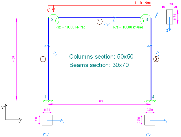
Sample frame with partial (semi-rigid) releases to analyze with 3D Frame Library (Metric units)
We will first create a new C# Windows Application project from Visual Studio and follow the following steps to carry out the structural analysis according the data provided. Please notice that we could use any other .NET compatible language and take the corresponding steps. The source code of all examples can be downloaded here.
Add a reference to 3D Frame Library
A reference to Frame 3D Library can easily be added by right clicking on the application project and selecting Add --> Reference.
Providing the data to 3D Frame Library using C#
New model definition
Model Model = new Model();
Model.LicenseInfo = LicenseInfo;
Definition of materials
//Create a new material for concrete
Material matConcrete = new Material();
matConcrete.Name = "Concrete";//Material name
matConcrete.Density = 2.5;//density in mass units/m3, for example tn/m3
matConcrete.G = 11538461;//shear modulus
matConcrete.E = 30000000;//elasticity modulus
Definition of cross section
//Create a new beam section of dimensions 30cmx70xm
FrameElementSection secBeam30_70 = new FrameElementSection();
secBeam30_70.Name = "Beam30/70";//section name
secBeam30_70.A = 0.3 * 0.7;//section area
secBeam30_70.Iy = 0.3 * 0.7 * 0.7 * 0.7 / 12;//inertia moment about local y axis
secBeam30_70.Iz = 0.8 * 0.3 * 0.3 * 0.3 / 12;//inertia moment about local z axis
secBeam30_70.It = 4.347e-3;//torsional constant
secBeam30_70.b = 0.30;//section height
secBeam30_70.h = 0.70;//section height

//Create a new beam section of dimensions 50cmx50xm
FrameElementSection secColumn50_50 = new FrameElementSection();
secColumn50_50.Name = "Column50/50";  //section name
secColumn50_50.A = 0.5 * 0.5;//section area
secColumn50_50.Iy = 0.5 * 0.5 * 0.5 * 0.5 / 12;//inertia moment about local y axis
secColumn50_50.Iz = 0.5 * 0.5 * 0.5 * 0.5 / 12;//inertia moment about local z axis
secColumn50_50.It = 8.8125e-3;
secColumn50_50.b = 0.50;//section height
secColumn50_50.h = 0.50;//section height
Definition of model geometry and loads
//Create node n1
Frame3D.SuperNode n1 = new Frame3D.SuperNode(1, 0, 0, 0);
n1.dof1constraint = true;//translational constraint in direction x at local system of node
n1.dof2constraint = true;//translational constraint in direction y at local system of node
n1.dof3constraint = true;//translational constraint in direction z at local system of node
n1.dof4constraint = true;//rotational constraint in direction x at local system of node
n1.dof5constraint = true;//rotational constraint in direction y at local system of node
n1.dof6constraint = true;//rotational constraint in direction z at local system of node
Model.InputNodes.Add(n1);

//Create node n2
Frame3D.SuperNode n2 = new Frame3D.SuperNode(2, 0, 4, 0);
Model.InputNodes.Add(n2);

//Create node n3
Frame3D.SuperNode n3 = new Frame3D.SuperNode(3, 5, 4, 0);
Model.InputNodes.Add(n3);

//Create node n4
Frame3D.SuperNode n4 = new Frame3D.SuperNode(4, 5, 0, 0);
n4.dof1constraint = true;//translational constraint in direction x at local system of node
n4.dof2constraint = true;//translational constraint in direction y at local system of node
n4.dof3constraint = true;//translational constraint in direction z at local system of node
n4.dof4constraint = true;//rotational constraint in direction x at local system of node
n4.dof5constraint = true;//rotational constraint in direction y at local system of node
n4.dof6constraint = true;//rotational constraint in direction z at local system of node
Model.InputNodes.Add(n4);

//Create frame element 1
FrameSuperElement el1 = new FrameSuperElement(1, n1, n2, new Geometry.XYZ(0, 0, 1), matConcrete, secColumn50_50, new MemberReleases(), new MemberReleases(), false, false);
Model.InputFiniteElements.Add(el1);

//Create a MemberRelases object. Release are defined in element local coordinate system.
MemberReleases PartialRelease = new MemberReleases();
PartialRelease.Name = "Partial bending release";//Name of the object
PartialRelease.rz = true;//Release the rotational degree of freedom about z axis (in element local coordinate system)
PartialRelease.krz = 10000;//Assign a spring stiffness (units in moment/rotations, for example kNm/rad)
//Note that the corresponding degree of freedom should be first released in order to define afterwards a partial stiffness constant
//In case of full release we should have given PartialRelease.krz = 0;

//Create frame element 2. Note that the proper release object (Partial Releases is passed in the constructor)
FrameSuperElement el2 = new FrameSuperElement(2, n2, n3, new Geometry.XYZ(0, 4, 1), matConcrete, secBeam30_70, PartialRelease, PartialRelease, false, false);
LinearLoadCaseForSuperFrameElement lc1 = new LinearLoadCaseForSuperFrameElement("lc1", LoadCaseType.DEAD);
lc1.UniformLoad.UniformLoadsY.Add(new FrameSuperUniformLoad(0, 1, -10, -10, LoadDefinitionFromStartingNode.Relatively, LoadCordinateSystem.Global));
el2.LinearLoadCasesList.Add(lc1);
Model.InputFiniteElements.Add(el2);

//Create frame element 3
FrameSuperElement el3 = new FrameSuperElement(3, n4, n3, new Geometry.XYZ(5, 0, 1), matConcrete, secColumn50_50, new MemberReleases(), new MemberReleases(), false, false);
Model.InputFiniteElements.Add(el3);
Call the solution method
Model.Solve();Obtain the analysis results
double[] Min, Max;

//Support reactions
n1.GetReactionsForLoadCase("lc1", out Min, out Max, 0);
double n1_Rtx_lc1 = Max[0];
n1.GetReactionsForLoadCase("lc1", out Min, out Max, 0);
double n1_Rty_lc1 = Max[1];
n4.GetReactionsForLoadCase("lc1", out Min, out Max, 0);
double n4_Rtx_lc1 = Max[0];
n4.GetReactionsForLoadCase("lc1", out Min, out Max, 0);
double n4_Rty_lc1 = Max[1];

//Rotations at nodes 2 and 3 (in local node system)
n2.GetNodalDisplacementsForLoadCase("lc1", out Min, out Max, 0);//negative rotation
double n2_Rrz_lc1 = Max[5];//negative rotation
n3.GetNodalDisplacementsForLoadCase("lc1", out Min, out Max, 0);//the same rotation, but positive
double n3_Rrz_lc1 = Max[5];//the same rotation, but positive