Example 9: Column under shear and large axial load (P-Δ effect) using 3D Frame Analysis Library
Example 9: Column under shear and large axial load (P-Δ effect) using 3D Frame Analysis Library
In this example, we will call the 3D Frame Library from a Visual Studio project and carry out the structural analysis of a simple column large compressive force in order to get its P-Δ effect. We will first provide the geometry, material properties and loads and afterwards call the corresponding routine in order to obtain the results.
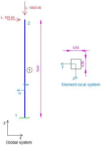
Sample column under large compressive load analyze with 3D Frame Library (Metric units)
We will first create a new C# Windows Application project from Visual Studio and follow the following steps to carry out the structural analysis according the data provided. Please notice that we could use any other .NET compatible language and take the corresponding steps. The source code of all examples can be downloaded here.
Add a reference to 3D Frame Library
A reference to Frame 3D Library can easily be added by right clicking on the application project and selecting Add --> Reference.
Providing the data to 3D Frame Library using C#
New model definition
Model Model = new Model();
Model.LicenseInfo = LicenseInfo;
Definition of materials
//Create a new material for concrete
Material matConcrete = new Material();
matConcrete.Name = "Concrete";//Material name
matConcrete.Density = 2.5;//density in mass units/m3, for example tn/m3
matConcrete.G = 11538461;//shear modulus
matConcrete.E = 30000000;//elasticity modulus
Definition of cross section
//Create a new column section of dimensions 50cmx50xm
FrameElementSection secCol050_50 = new FrameElementSection();
secCol050_50.Name = "Column50/50";//section name
secCol050_50.A = 0.5 * 0.5;//section area
secCol050_50.Iy = 0.5 * 0.5 * 0.5 * 0.5 / 12;//inertia moment about local y axis
secCol050_50.Iz = 0.5 * 0.5 * 0.5 * 0.5 / 12;//inertia moment about local z axis
secCol050_50.It = 4.347e-3;//torsional constant
secCol050_50.b = 0.5;//section height
secCol050_50.h = 0.5;//section height
Definition of model geometry and static loads
//-------MODEL GEOMETRY AND LOADS DEFINITION-------

//First node creation
Frame3D.SuperNode n1 = new Frame3D.SuperNode(1, 0, 0, 0);
//Application of supports (fixed conditions out of plane)
n1.dof1constraint = true;
n1.dof2constraint = true;
n1.dof3constraint = true;
n1.dof4constraint = true;
n1.dof5constraint = true;
n1.dof6constraint = true;
Model.InputNodes.Add(n1);

//Second node creation
Frame3D.SuperNode n2 = new Frame3D.SuperNode(2, 0, 0, 5);
//Application of supports (fixed conditions out of plane)
n2.dof1constraint = false;
n2.dof2constraint = true;
n2.dof3constraint = false;
n2.dof4constraint = true;
n2.dof5constraint = false;
n2.dof6constraint = true;

//Load case creation for horizontal and vertical load acting at top node
LinearLoadCaseForSuperNode L = new LinearLoadCaseForSuperNode("L", LoadCaseType.OTHER);
L.Px = 100;
L.Pz = -1000;
n2.LinearLoadCasesList.Add(L);
Model.InputNodes.Add(n2);

FrameSuperElement el1 = new FrameSuperElement(1, n1, n2, new Geometry.XYZ(0, 1, 0), matConcrete, secCol050_50, new MemberReleases(), new MemberReleases(), false, false);

Model.InputFiniteElements.Add(el1);
Definition of geometric non linear case
//Creation of a geometric non linear case
GeometricNonLinearCase NLcase = new GeometricNonLinearCase("NL");
//Analysis parameters:
NLcase.LoadSteps = 50;//50 load steps
NLcase.IterationsPerLoadStep = 30;//maximum 30 iteration per load step
NLcase.ConvergenceTolerance = 1e-12;//convergence tolerance in terms of force
//It will include the loads that have been defined as "L"
NLcase.InputLoadCombo = new LoadCombination("NLcase loads", ComboType.ADD);
NLcase.InputLoadCombo.Items.Add(new LoadCaseWithFactor("L", 1));
//Definition of stiffness matrix update mode
NLcase.UpdateStiffnessMethod = GeometricNonLinearCase.UpdateStiffnessMatrixMethod.AfterEachIterationInLoadStep;
NLcase.SaveResultsAtEachLoadStep = true;//Results will be saved at all intermediate load steps
Model.GeometricNonLinearCases.Add(NLcase);
Call the solution method
Model.Solve();Obtain the analysis results
double[] Min, Max;
for (int loadStep = 1; loadStep <= NLcase.LoadSteps; loadStep++)
{
    //Get horizontal displacement of top node of the column at each load step
    n2.GetNodalDisplacementsForLoadCase("NL", out Min, out Max, loadStep);
    double horDisplacement = Min[0];

    //Get bending moment at the base of the column at each load step
    el1.GetInternalForcesForLoadCase(0, "NL", out Min, out Max, loadStep);
    double BaseMoment = Min[4];
}