Software for the Analysis and Design of structural cross sections
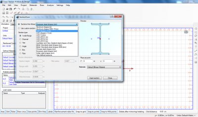
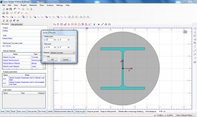
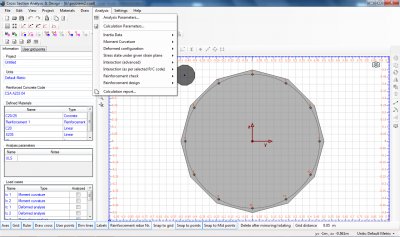
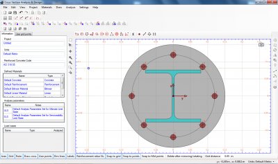
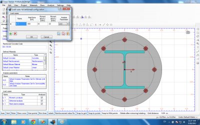
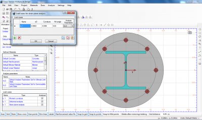
Cross Section Analysis & Design (top rated structural software in America, Europe, Asia and Australia) is a powerful application that can perform a wide range of cross section calculations, including the design of reinforced concrete sections (rebar calculator). The provided cross sections can be simple or complex and can consist of one or more geometric entities (rectangles, polygons, circles, arcs etc.). The geometry of the cross section can simply be drawn using the versatile featured user interface. The user can also import standard steel sections from a complete shape library according to all major codes (AISC, Australian-New Zealand, BS, Chinese, European, Indian, Aluminum etc.)
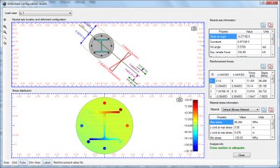
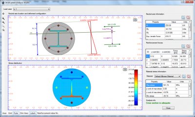
There are no limitations regarding the shape, materials or loads of a section, as the program can handle any arbitrary cross section under biaxial bending and axial loads (Mx,My,P). Among its capabilities, Cross Section Analysis & Design can calculate all sectional properties, plot Moment – Curvature and Interaction diagrams, estimate the location of the neutral axis under given sets of biaxial loads and plot the corresponding strain diagrams as well as the resulting stress contours. These items can also be calculated by providing the location of the neutral axis plane on the section.
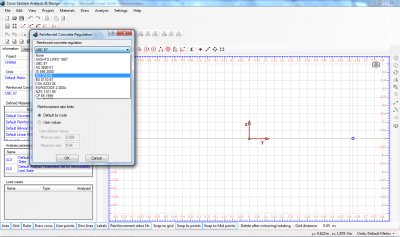
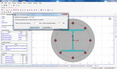
Moreover, the program fully complies with the following codes concerning reinforced concrete sections: AASHTO, UBC, AS 3600, IS 456, ACI 318, BS 8110, CSA A233, EC2, NZS 3101, CP 65.
With just a few clicks, the user can perform a reinforcement design according to above listed codes, plot the matching interaction diagrams etc., or check a given reinforcement pattern under the specified load cases.
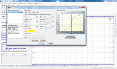
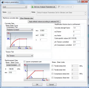
The stress – strain curves of concrete, reinforcement and other materials are specified parametrically using Analysis Parameters Sets. Each load case is assigned with an Analysis Parameters Set, so that calculations can be performed for many design situations, such as Ultimate/Serviceability or custom defined Limit States, with an automatic adjustment of the material properties, safety factors etc. For instance, when choosing the default ULS Parameters Set, the concrete curve will be rectangular and its tensile strength will not be considered. On the other hand, the default SLS Parameters Set, uses a hyperbolic stress-strain curve for concrete taking into account its tensile strength. The safety factors in this case are automatically adjusted to be 1.0. These parameters can be directly changed by the user.
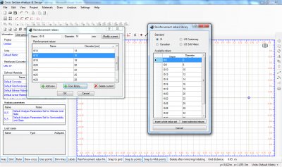
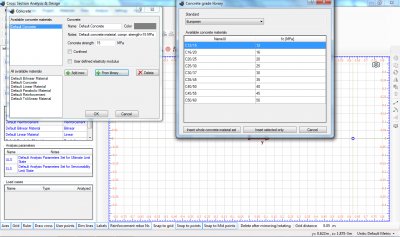
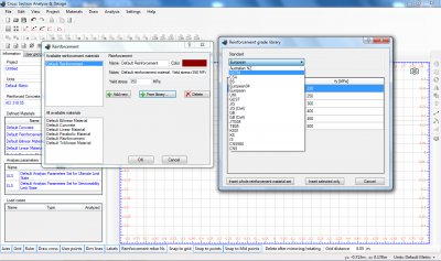
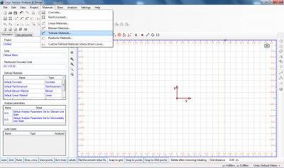
A large material library is also available according to almost all concrete/reinforcement material specifications. Apart from concrete and reinforcement materials, the user can also specify custom linear, bilinear, trilinear parabolic or fully general materials.
The program is compatible with Windows XP/Vista/7/8/8.1/10/11, 32/64 bit.
Analysis features
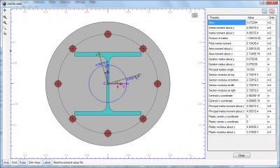
- Section properties calculations (with regard to a user defined base material or the geometric properties of the section) including inertia data, elastic and plastic elasticity moduli, etc. In more detail, the program can calculate the centroidal axis locations, moments of inertia, radius of gyration, section moduli and product moment of inertia for any shape. Shapes can be constructed using general shapes (polygons, circles, arcs, etc.) as well as standard shapes (wide flanges, angles, channels, tubes, etc.). Section properties are computed for reinforced concrete and composite membersas well. Multiple material equivalent sections are also handled easily.
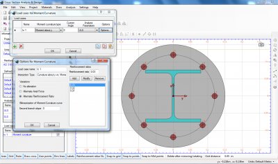
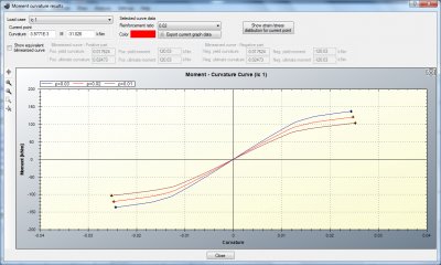
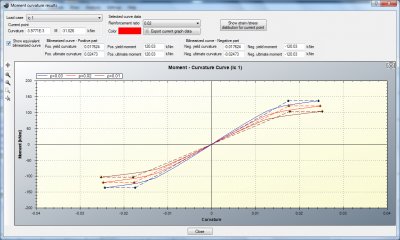
- Calculation and plotting of the Moment vs. Curvature diagram for bending about a predefined axis. Accordingly, a Force vs. Axial strain diagram can be created.
- Calculation of the equivalent bilinear Moment vs. Curvature graph with or without hardening and estimation of the yield/ultimate curvatures and moments.
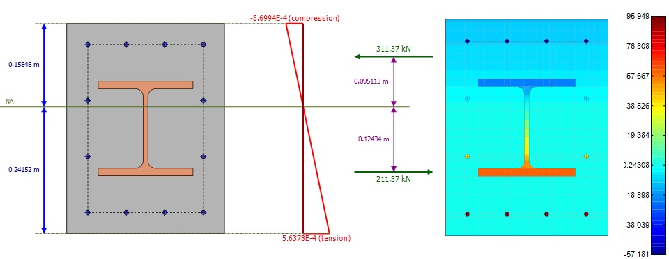
- Estimation of the neutral axis, strain distribution and plotting of stress contour under the given sets of biaxial loads. Reporting of reinforcement forces and the locations of maximum/minimum stresses for each material of the section.
- Estimation of the biaxial applied forces under a given neutral axis (location, orientation and curvature). As in previous case, the strain distribution and a stress contour are plotted. Moreover, the reinforcement forces are reported and the maximum/minimum stress locations for each material in the section are computed.
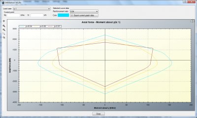
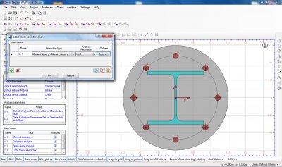
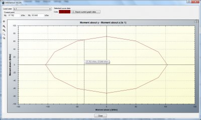
- Advanced Interaction Diagram Analysis. The failure surface is calculated and plotted in terms of: Moment vs. Axial force or Moment vs. Moment. The user can specify different values for reinforcement ratios (if rebars have been provided) or axial force values, so that multiple curves can be plotted in one graph. This analysis type is generic and can be used to excerpt the interaction diagram and section capacities of any generic section with any material, shape etc.
- Interaction diagram as per specified Reinforced Concrete Code. The program computes the interaction diagram as explained before, but applies all related regulation checks, stress distributions, safety factors etc., according to the selected code (AASHTO, UBC, AS 3600, IS 456, ACI 318, BS 8110, CSA A233, EC2, NZS 3101 and CP 65).
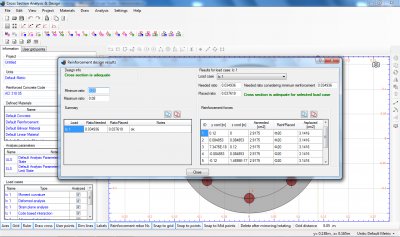
- Reinforcement Design. The provided reinforcement is designed, so that the required rebar diameters are selected. This procedure takes place in accordance to the provided regulation (AASHTO, UBC, AS 3600, IS 456, ACI 318, BS 8110, CSA A233, EC2, NZS 3101 and CP 65).
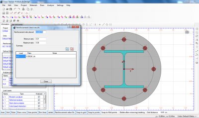
- Reinforcement Check. The given reinforcement pattern is checked and a capacity ratio of the cross section is reported. Reinforcement check and design features make this application a unique rebar calculator as well.
Pre-processing features
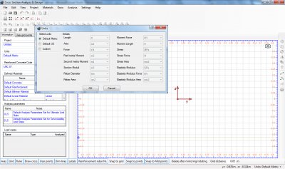
- All major systems of units are supported (Metric, US, User defined)
- Top quality graphics rendering
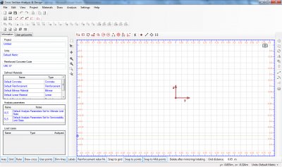
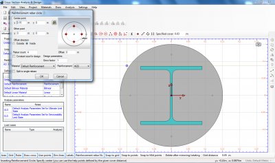
- Full Graphical User Interface including zoom, pan, grid, snap options etc.
- Every user action can be done graphically at real time
- Library with all major steel section shapes (AISC, Australian-New Zealand, BS, Chinese, European, Indian, Aluminum etc.)
- Library with all major concrete and reinforcement grades, as well as other materials such as cold formed/hot rolled steel, timber etc.
- Use of linear, bilinear, trilinear and parabolic materials
- Definition of custom materials by providing a relevant stress strain curve
- Definition and use of Analysis Parameters sets. In order to simulate different limit states for the analysis/design of the cross section, the user can use the existing sets ULS (Ultimate Limit State) or SLS (Serviceability Limit State), override them or add more sets of Analysis Parameters. Each set defines the concrete stress distribution at compressive or tensile zones, the safety factors to be used and all preferences regarding the steel reinforcement behavior in the calculations. Apart from these, the user can define his preferences for the remaining non steel/reinforcement materials (if any) in the section. Each load case is assigned with an Analysis Parameters set, so that the appropriate considerations are considered in the calculations.
- Automatic calculation of the minimum and maximum reinforcement ratio for a given cross section as per the specified Reinforced Concrete regulation. These values are considered for Reinforcement Design.
Post-processing features
- Comprehensive and versatile reporting of the results
- Automatic creation of high-quality, editable calculation report that can be exported to Word (doc), Excel (xls) and Adobe PDF (pdf) formats. Diagrams, plots and color contours are included in the report
- Creation of fully customizable graphs (Moment vs. Curvature, Interaction etc.) as well as stress contours and strain distribution
- Reporting of neutral axis information, reinforcement forces and material stress information
- Rebar calculation results (an existing rebar pattern is checked, or needed rebars are calculated and placed automatically) for the provided Limit States (ULS, SLS and other states defined by the user)
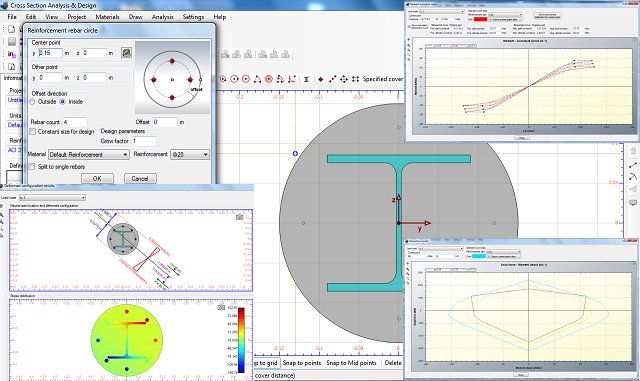
Screenshots