Example 7: Simple 3D building with rigid floor diaphragms and Response Spectrum Analysis using 3D Frame Analysis Library
Example 7: Simple 3D building with rigid floor diaphragms and Response Spectrum Analysis using 3D Frame Analysis Library
In this example, we will call the 3D Frame Library from a Visual Studio project and carry out the structural analysis of a simple 3d building with rigid floor diaphragms. We will also apply a dynamic load (response spectrum case) in order to simulate the quake. We will first provide the geometry, material properties, response function and loads and afterwards call the corresponding routine in order to obtain the results.
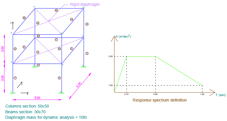
Sample 3d building with rigid diaphragms to analyze with 3D Frame Library (Metric units)
We will first create a new C# Windows Application project from Visual Studio and follow the following steps to carry out the structural analysis according the data provided. Please notice that we could use any other .NET compatible language and take the corresponding steps. The source code of all examples can be downloaded here.
Add a reference to 3D Frame Library
A reference to Frame 3D Library can easily be added by right clicking on the application project and selecting Add --> Reference.
Providing the data to 3D Frame Library using C#
New model definition
Model Model = new Model();
Model.LicenseInfo = LicenseInfo;
Definition of materials
//Create a new material for concrete
Material matConcrete = new Material();
matConcrete.Name = "Concrete";//Material name
matConcrete.Density = 2.5;//density in mass units/m3, for example tn/m3
matConcrete.G = 11538461;//shear modulus
matConcrete.E = 30000000;//elasticity modulus
Definition of cross section
//Create a new beam section of dimensions 30cmx70xm
FrameElementSection secBeam30_70 = new FrameElementSection();
secBeam30_70.Name = "Beam30/70";//section name
secBeam30_70.A = 0.3 * 0.7;//section area
secBeam30_70.Iy = 0.3 * 0.7 * 0.7 * 0.7 / 12;//inertia moment about local y axis
secBeam30_70.Iz = 0.8 * 0.3 * 0.3 * 0.3 / 12;//inertia moment about local z axis
secBeam30_70.It = 4.347e-3;//torsional constant
secBeam30_70.b = 0.30;//section height
secBeam30_70.h = 0.70;//section height

//Create a new beam section of dimensions 50cmx50xm
FrameElementSection secColumn50_50 = new FrameElementSection();
secColumn50_50.Name = "Column50/50";  //section name
secColumn50_50.A = 0.5 * 0.5;//section area
secColumn50_50.Iy = 0.5 * 0.5 * 0.5 * 0.5 / 12;//inertia moment about local y axis
secColumn50_50.Iz = 0.5 * 0.5 * 0.5 * 0.5 / 12;//inertia moment about local z axis
secColumn50_50.It = 8.8125e-3;
secColumn50_50.b = 0.50;//section height
secColumn50_50.h = 0.50;//section height
Definition of model geometry
//Create node n1
Frame3D.SuperNode n1 = new Frame3D.SuperNode(1, 0, 0, 0);
n1.dof1constraint = true;//translational constraint in direction x at local system of node
n1.dof2constraint = true;//translational constraint in direction y at local system of node
n1.dof3constraint = true;//translational constraint in direction z at local system of node
n1.dof4constraint = true;//rotational constraint in direction x at local system of node
n1.dof5constraint = true;//rotational constraint in direction y at local system of node
n1.dof6constraint = true;//rotational constraint in direction z at local system of node
Model.InputNodes.Add(n1);

//Create node n2
Frame3D.SuperNode n2 = new Frame3D.SuperNode(2, 5, 0, 0);
n2.dof1constraint = true;//translational constraint in direction x at local system of node
n2.dof2constraint = true;//translational constraint in direction y at local system of node
n2.dof3constraint = true;//translational constraint in direction z at local system of node
n2.dof4constraint = true;//rotational constraint in direction x at local system of node
n2.dof5constraint = true;//rotational constraint in direction y at local system of node
n2.dof6constraint = true;//rotational constraint in direction z at local system of node
Model.InputNodes.Add(n2);

//Create node n3
Frame3D.SuperNode n3 = new Frame3D.SuperNode(3, 0, 6, 0);
n3.dof1constraint = true;//translational constraint in direction x at local system of node
n3.dof2constraint = true;//translational constraint in direction y at local system of node
n3.dof3constraint = true;//translational constraint in direction z at local system of node
n3.dof4constraint = true;//rotational constraint in direction x at local system of node
n3.dof5constraint = true;//rotational constraint in direction y at local system of node
n3.dof6constraint = true;//rotational constraint in direction z at local system of node
Model.InputNodes.Add(n3);

//Create node n4
Frame3D.SuperNode n4 = new Frame3D.SuperNode(4, 5, 6, 0);
n4.dof1constraint = true;//translational constraint in direction x at local system of node
n4.dof2constraint = true;//translational constraint in direction y at local system of node
n4.dof3constraint = true;//translational constraint in direction z at local system of node
n4.dof4constraint = true;//rotational constraint in direction x at local system of node
n4.dof5constraint = true;//rotational constraint in direction y at local system of node
n4.dof6constraint = true;//rotational constraint in direction z at local system of node
Model.InputNodes.Add(n4);

//Create node n5
Frame3D.SuperNode n5 = new Frame3D.SuperNode(5, 0, 0, 3);
Model.InputNodes.Add(n5);

//Create node n6
Frame3D.SuperNode n6 = new Frame3D.SuperNode(6, 5, 0, 3);
Model.InputNodes.Add(n6);

//Create node n7
Frame3D.SuperNode n7 = new Frame3D.SuperNode(7, 0, 6, 3);
Model.InputNodes.Add(n7);

//Create node n8
Frame3D.SuperNode n8 = new Frame3D.SuperNode(8, 5, 6, 3);
Model.InputNodes.Add(n8);

//Create node n9
Frame3D.SuperNode n9 = new Frame3D.SuperNode(9, 0, 0, 6);
Model.InputNodes.Add(n9);

//Create node n10
Frame3D.SuperNode n10 = new Frame3D.SuperNode(10, 5, 0, 6);
Model.InputNodes.Add(n10);

//Create node n11
Frame3D.SuperNode n11 = new Frame3D.SuperNode(11, 0, 6, 6);
Model.InputNodes.Add(n11);

//Create node n12
Frame3D.SuperNode n12 = new Frame3D.SuperNode(12, 5, 6, 6);
Model.InputNodes.Add(n12);


//Create frame elements (Note the definition of the auxiliary point which is different for each frame in order to correclty place it
//It is reminded that auxiliary point is only only used to define the rotation of the frame element about its longitudinal axis
//This point should not belong to the longitudinal axis of the element. In such case, arithmetic errors would occur.


//Create first story columns

FrameSuperElement el1 = new FrameSuperElement(1, n1, n5, new Geometry.XYZ(0, 1, 0), matConcrete, secColumn50_50, new MemberReleases(), new MemberReleases(), false, false);
Model.InputFiniteElements.Add(el1);
FrameSuperElement el2 = new FrameSuperElement(2, n2, n6, new Geometry.XYZ(5, 1, 0), matConcrete, secColumn50_50, new MemberReleases(), new MemberReleases(), false, false);
Model.InputFiniteElements.Add(el2);
FrameSuperElement el3 = new FrameSuperElement(3, n4, n8, new Geometry.XYZ(5, 7, 0), matConcrete, secColumn50_50, new MemberReleases(), new MemberReleases(), false, false);
Model.InputFiniteElements.Add(el3);
FrameSuperElement el4 = new FrameSuperElement(4, n3, n7, new Geometry.XYZ(0, 7, 0), matConcrete, secColumn50_50, new MemberReleases(), new MemberReleases(), false, false);
Model.InputFiniteElements.Add(el4);


//Create first story beams

FrameSuperElement el5 = new FrameSuperElement(5, n5, n6, new Geometry.XYZ(0, 1, 3), matConcrete, secColumn50_50, new MemberReleases(), new MemberReleases(), false, false);
Model.InputFiniteElements.Add(el5);
FrameSuperElement el6 = new FrameSuperElement(6, n6, n8, new Geometry.XYZ(4, 0, 3), matConcrete, secColumn50_50, new MemberReleases(), new MemberReleases(), false, false);
Model.InputFiniteElements.Add(el6);
FrameSuperElement el7 = new FrameSuperElement(7, n7, n8, new Geometry.XYZ(0, 7, 3), matConcrete, secColumn50_50, new MemberReleases(), new MemberReleases(), false, false);
Model.InputFiniteElements.Add(el7);
FrameSuperElement el8 = new FrameSuperElement(8, n5, n7, new Geometry.XYZ(-1, 0, 3), matConcrete, secColumn50_50, new MemberReleases(), new MemberReleases(), false, false);
Model.InputFiniteElements.Add(el8);

//Create second story columns

FrameSuperElement el13 = new FrameSuperElement(13, n9, n10, new Geometry.XYZ(0, 1, 3), matConcrete, secColumn50_50, new MemberReleases(), new MemberReleases(), false, false);
Model.InputFiniteElements.Add(el13);
FrameSuperElement el14 = new FrameSuperElement(14, n10, n12, new Geometry.XYZ(4, 0, 3), matConcrete, secColumn50_50, new MemberReleases(), new MemberReleases(), false, false);
Model.InputFiniteElements.Add(el14);
FrameSuperElement el15 = new FrameSuperElement(15, n11, n12, new Geometry.XYZ(0, 7, 3), matConcrete, secColumn50_50, new MemberReleases(), new MemberReleases(), false, false);
Model.InputFiniteElements.Add(el15);
FrameSuperElement el16 = new FrameSuperElement(16, n9, n11, new Geometry.XYZ(-1, 0, 3), matConcrete, secColumn50_50, new MemberReleases(), new MemberReleases(), false, false);
Model.InputFiniteElements.Add(el16);

//Create second story beams

FrameSuperElement el9 = new FrameSuperElement(9, n5, n9, new Geometry.XYZ(0, 1, 3), matConcrete, secColumn50_50, new MemberReleases(), new MemberReleases(), false, false);
Model.InputFiniteElements.Add(el9);
FrameSuperElement el10 = new FrameSuperElement(10, n6, n10, new Geometry.XYZ(5, 1, 3), matConcrete, secColumn50_50, new MemberReleases(), new MemberReleases(), false, false);
Model.InputFiniteElements.Add(el10);
FrameSuperElement el11 = new FrameSuperElement(11, n8, n12, new Geometry.XYZ(5, 7, 3), matConcrete, secColumn50_50, new MemberReleases(), new MemberReleases(), false, false);
Model.InputFiniteElements.Add(el11);
FrameSuperElement el12 = new FrameSuperElement(12, n7, n11, new Geometry.XYZ(0, 7, 3), matConcrete, secColumn50_50, new MemberReleases(), new MemberReleases(), false, false);
Model.InputFiniteElements.Add(el12);
Definition of floor diaphragms
//Create a list of Geometry.XY objects with the boundary points of the floor diaphragms
//A polygon is then internally defined and all points that liew it it or on its edges will be assumed to be restarined by the diaphragm
List<Geometry.XY> Pts = new List<Geometry.XY>();
//Points should be given anti-clockwise
//Points are given in plan view (x-y)
//Points (if more than 3) should lie on the same plane
Pts.Add(new Geometry.XY(0, 0));
Pts.Add(new Geometry.XY(5, 0));
Pts.Add(new Geometry.XY(5, 6));
Pts.Add(new Geometry.XY(0, 6));

//Floor diaphragm definition. Note that the 3rd argument specifies the z-coordinate of diaphragm
//Floor diaphragm is defined in xy plane only. Global Z axis is always perpendicular to the plane that the diaphragm points define
FloorDiaphragm fd1 = new FloorDiaphragm(1, Pts, 3);
//Create a load case than specifies the mass source for the diaphragm
//This load case only defines the mass for the diaphragm and is only needed in dynamic analysis.
//Vertical static loads are not taken into account from this load case.
//If a diaphragm is loaded, the corresponding mass load case should be assigned. Then the diaphragm mass will be considered for the dynamic analysis
//A load case for the perimetric beams should then manually be created, which will distribute the diaphragm loads to the frames. This is not made automatically by the library
LinearLoadCaseForFloorDiaphragm mass_fd1 = new LinearLoadCaseForFloorDiaphragm("mass source", LoadCaseType.DEAD);
mass_fd1.pz = 5;//units in force/area, for example kN/m2, positive direction = gravity
fd1.LinearLoadCasesList.Add(mass_fd1);
Model.FloorDiaphragms.Add(fd1);
//Similarily create a floor diaphragm for second story
FloorDiaphragm fd2 = new FloorDiaphragm(2, Pts, 6);
LinearLoadCaseForFloorDiaphragm mass_fd2 = new LinearLoadCaseForFloorDiaphragm("mass source", LoadCaseType.DEAD);
mass_fd2.pz = 2;//units in force/area, for example kN/m2, positive direction = gravity
fd2.LinearLoadCasesList.Add(mass_fd2);
Model.FloorDiaphragms.Add(fd2);
Definition of seismic mass
//Define a load combination for the mass for the diaphragms (for example DEAD+0.5LIVE etc)
LoadCombination MassCombo = new LoadCombination("mass combo", ComboType.ADD);
MassCombo.Items.Add(new LoadCaseWithFactor("mass source", 1.0));
Model.MassSourceCombination = MassCombo;

//Specify how mass is going to be calculated
GeneralData.IncludeAdditionalMassesInMassSource = true;
GeneralData.IncludeLoadsInMassSource = true;
GeneralData.IncludeSelfWeightInMassSource = true;
Definition of response spectrum function and case
//Create a response spectrum function
ResponseSpectrumFunction RSFunction = new ResponseSpectrumFunction("RS function");
RSFunction.RS_T = new double[] { 0, 0.15, 0.50, 1.20 };//T (time) values of point of the spectrum (in sec)
RSFunction.RS_A = new double[] { 0, 5.5, 5.5, 1.0 };//A (spectral acceleration) values of points in spectrum (in length/sec2, for example m/sec2)

//Create a response spectrum case and specify the application direction and the modal combination rule (SRSS or CQC)
ResponseSpectrumCase RSCase = new ResponseSpectrumCase("RScase", GroundMotionDirection.UX, ModeComboType.CQC);
RSCase.DiaphragmEccentricityRatio = 0.05;//Specify diaphragm eccentricity ratio (usually 5%-10%). This value will produce a torsional about the global Z coordinate at the center of mass of each diaphragm.
RSCase.RSFunction = RSFunction;//Assign the previously defined response spectrum
Model.ResponseSpectrumCases.Add(RSCase);//Add to model

Model.NrOfModesToFind = 6;
Call the solution method
Model.Solve();Obtain the analysis results
//Effective mass ratio calculation:
double Effmx = Model.TotalEffectiveMassUX;//mass excited in x direction
double Effmy = Model.TotalEffectiveMassUY;//mass excited in y direction
double Massmx = Model.TotalMassUX;//total lateral mass in x direction
double Massmy = Model.TotalMassUY;//total lateral mass in y direction
double ratio_mass_x = Effmx / Massmx;//>90% of the total mass is excited by the response spectrum analysis
double ratio_mass_y = Effmy / Massmy;//>90% of the total mass is excited by the response spectrum analysis

//Reactions (Note that all results are now envelopes beacuse they came from a dynamic analysis)
double[] Min1, Max1;
double[] Min2, Max2;
double[] Min3, Max3;
double[] Min4, Max4;
n1.GetReactionsForLoadCase(RSCase.name, out Min1, out Max1, 0);
n2.GetReactionsForLoadCase(RSCase.name, out Min2, out Max2, 0);
n3.GetReactionsForLoadCase(RSCase.name, out Min3, out Max3, 0);
n4.GetReactionsForLoadCase(RSCase.name, out Min4, out Max4, 0);

//Modal information
double[,] Modes = Model.Modes;//each rows represents each degree of freedom, each column represents the corresponding modal displacements

//Periods
double[] Periods = Model.Periods;//each entry represents the period of the corresponding node

//Element 2 (el2) internal forces for response spectrum case
double[] Min, Max;
el2.GetInternalForcesForLoadCase(0, "RScase", out Min, out Max, 0);