Example 3: Node local coordinate system (skew support) using 3D Frame Analysis Library
Example 3: Node local coordinate system (skew support) using 3D Frame Analysis Library
In this example, we will call the 3D Frame Library from a Visual Studio project and carry out the structural analysis of a simple beam on a skew support. We will first provide the geometry, material properties and loads and afterwards call the corresponding routine in order to obtain the results.
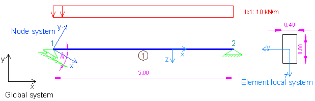
Sample beam with skew support according to the local coordinate system of the first node to analyze with 3D Frame Library (Metric units)
We will first create a new C# Windows Application project from Visual Studio and follow the following steps to carry out the structural analysis according the data provided. Please notice that we could use any other .NET compatible language and take the corresponding steps. The source code of all examples can be downloaded here.
Add a reference to 3D Frame Library
A reference to Frame 3D Library can easily be added by right clicking on the application project and selecting Add --> Reference.
Providing the data to 3D Frame Library using C#
New model definition
Model Model = new Model();
Model.LicenseInfo = LicenseInfo;
Definition of materials
//Create a new material for concrete
Material matConcrete = new Material();
matConcrete.Name = "Concrete";//Material name
matConcrete.Density = 2.5;//density in mass units/m3, for example tn/m3
matConcrete.G = 11538461;//shear modulus
matConcrete.E = 30000000;//elasticity modulus
Definition of cross section
//Create a new beam section of dimensions 40cmx80xm
FrameElementSection secBeam40_80 = new FrameElementSection();
secBeam40_80.Name = "Beam40/80";//section name
secBeam40_80.A = 0.4 * 0.8;//section area
secBeam40_80.Iy = 0.4 * 0.8 * 0.8 * 0.8 / 12;//inertia moment about local y axis
secBeam40_80.Iz = 0.8 * 0.4 * 0.4 * 0.4 / 12;//inertia moment about local z axis
secBeam40_80.It = 0.0117248;//torsional constant
secBeam40_80.b = 0.40;//section height
secBeam40_80.h = 0.80;//section height
Definition of model geometry and loads
//Create node n1, the local coordinate system of the node is assigned, which means that it is different from the default global system.
//In order to define the new system, a new LocalCoordinateSystem is passed in the corresponding constructor of SuperNode object
//The first two point of this constructor define the local x axis of the node system and the third one defines the coordinates of an auxiliary
//point that lies in local XY plane
Frame3D.SuperNode n1 = new Frame3D.SuperNode(1, 0, 0, 0, new LocalCoordinateSystem(new Geometry.XYZ(0, 0, 0), new Geometry.XYZ(1, Math.Tan(-Math.PI / 6), 0), new Geometry.XYZ(1, Math.Tan(60.0 / 180 * Math.PI), 0)));
n1.dof2constraint = true;//translational constraint in direction y at local system (which was defined previously) of node
n1.dof3constraint = true;//translational constraint in direction z at local system of node
n1.dof4constraint = true;//rotational constraint in direction x at local system of node
n1.dof5constraint = true;//rotational constraint in direction y at local system of node
Model.InputNodes.Add(n1);

//Create node n2
Frame3D.SuperNode n2 = new Frame3D.SuperNode(2, 5, 0, 0);
n2.dof1constraint = true;//translational constraint in direction x at local system of node
n2.dof2constraint = true;//translational constraint in direction y at local system of node
n2.dof3constraint = true;//translational constraint in direction z at local system of node
n2.dof4constraint = true;//rotational constraint in direction x at local system of node
n2.dof5constraint = true;//rotational constraint in direction y at local system of node
Model.InputNodes.Add(n2);

//Create frame element 1
FrameSuperElement el1 = new FrameSuperElement(1, n1, n2, new Geometry.XYZ(0, 0, 1), matConcrete, secBeam40_80, new MemberReleases(), new MemberReleases(), false, false);

LinearLoadCaseForSuperFrameElement lc1 = new LinearLoadCaseForSuperFrameElement("lc1", LoadCaseType.DEAD);
lc1.UniformLoad.UniformLoadsY.Add(new FrameSuperUniformLoad(0, 1, -10, -10, LoadDefinitionFromStartingNode.Relatively, LoadCordinateSystem.Global));
el1.LinearLoadCasesList.Add(lc1);

Model.InputFiniteElements.Add(el1);
Call the solution method
Model.Solve();Obtain the analysis results
//Support reactions (Note that they are defined in the node local system)
n1.GetReactionsForLoadCase("lc1", out Min, out Max, 0);
double n1_Rty_lc1 = Max[1];
n2.GetReactionsForLoadCase("lc1", out Min, out Max, 0);//Axial force is acting on the element because of the skew support at node 1
double n2_Rtx_lc1 = Max[0];
n2.GetReactionsForLoadCase("lc1", out Min, out Max, 0);
double n2_Rty_lc1 = Max[1];