Example 14: Check of a timber cross section
Watch the video of this example >
Data for Cross Section Analysis & Design application
In this example, we are about to draw a timber cross section and check its adequacy under given external loads.
Wood grade: C20 solid wood, according to EN 338
Partial safety factor for solid timber: 1.3
Load cases
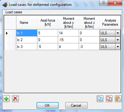
| lc 1: | N = 5 kN | My = 14 kNm | Mz = 0 |
| lc 2: | N = 0 | My = -15 kNm | Mz = 0 |
| lc 3: | N = -5 kN | My = 4 | Mz = 3 kNm |
Solution with Cross Section Analysis & Design
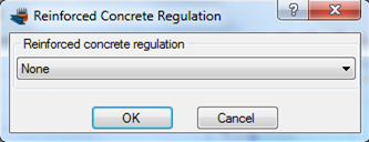
Setting Reinforced Concrete Code to None
Since the cross section does not have a concrete part, we can optionally set the Reinforced Concrete code to “None”, in order to hide all data related to reinforced concrete analysis. We click on Project -> Reinforced Concrete code menu item and select “None” as below.
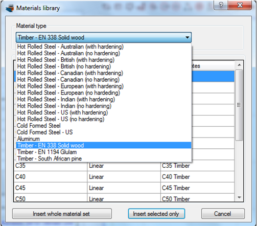
Definition of material properties
Next, we are going to specify the material properties.
The C20 solid wood grade can be imported from the library of the program by clicking on the Materials -> Import from Library menu item. From the top list we select “Timber – EN 338 Solid wood” in order to view the materials belonging to this collection.
Then, we can select the property C20 and click on “Insert selected only” button to use this material in our project.
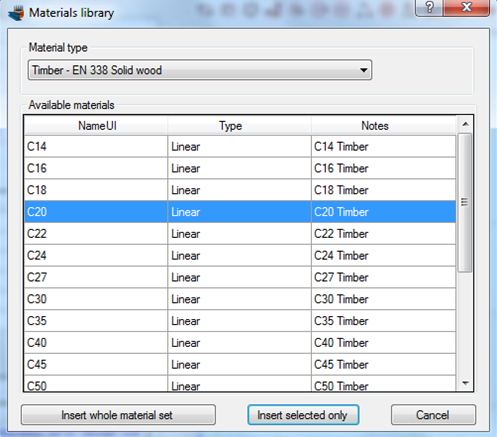
C20 wood has been imported in our project. We can view/change its properties by clicking on it from the list of the main form, as shown in the picture below.

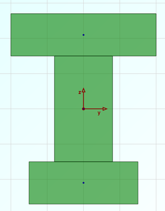
Drawing the geometry
First we will draw the web of the Tee section. To do this, we click on Draw -> Rectangle using dimensions from the top menu.
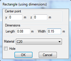
The center point of the rectangular section can be inserted by entering its coordinates (0,0) and then clicking the  button, or just by clicking on the point (0,0) with the mouse. Then the Length and Width values should be set to 0.08 and 0.15 respectively. Finally, the material C20 should be selected for the rectangle we are drawing.
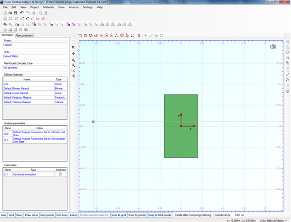
The web should now appear in the drawing area.
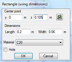
Next, we can draw the top flange by using the same command (Draw -> Rectangle using dimensions).
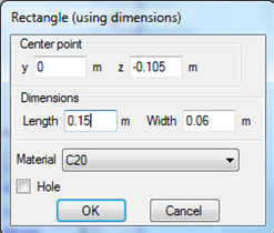
On the forms that shows, we enter the coordinates of the top flange center (0,0.105) and click the button. Then we specify the values for length and width and click OK.
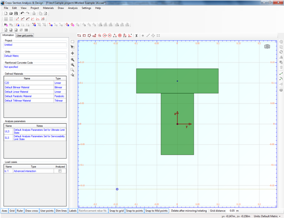
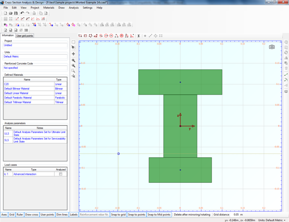
The cross section is shown in the drawing screen as follows.
Finally, we repeat the last action to draw the bottom flange.
After clicking OK, we can see the final geometry of the cross section in the drawing area.
Review of Analysis Parameters
In order to review the Analysis Parameters, we click on the Analysis -> Analysis Parameters menu item. The reinforced concrete related parameters are hidden, since no concrete regulation has been selected.
While the “ULS” set is active, we select the C20 wood grade from the list on the left and change the partial safety factor to 1.3 as shown in the picture below.
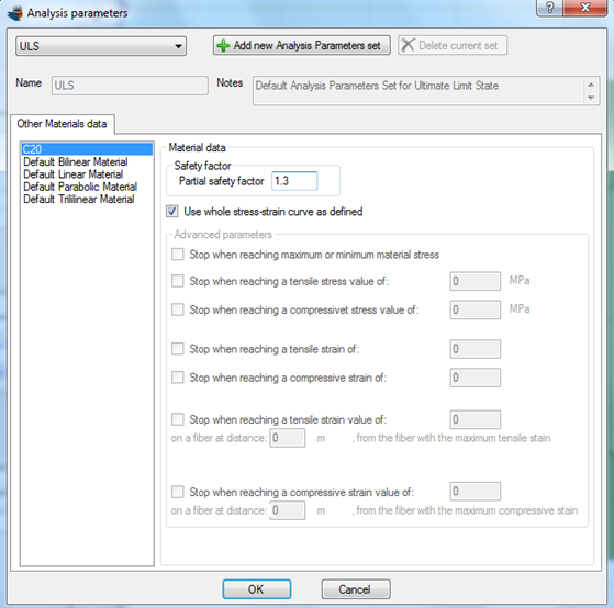
We click OK to close the form.
Definition of load cases
We will first define the load cases by clicking on the Analysis -> Deformed configuration -> Load cases menu item.
The load cases can be defined by successively clicking on the  button. We have to make sure that the “ULS” Analysis Parameters set have been assigned to each load case.
Carry out the analysis
We just click Analysis -> Deformed configuration -> Analyze, to perform the analysis.
Results
The calculated data can be found by clicking on Analysis -> Deformed configuration -> Show results menu item.
Results for load case lc1:
We choose “lc1” from the list at the top right corner of the form. The corresponding strain distribution and stress contour are shown. Moreover, information about the maximum/minimum stresses developed on the section can be found on the right.
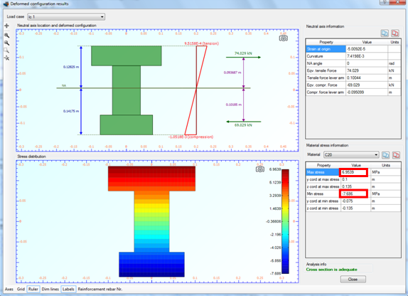
| Design for load case lc1: | adequate |
| Maximum stress: | 6.95 MPa at point (0.1,0.135) |
| Minimum stress: | -7.89 MPa at point (-0.075,-0.135) |
Results for load case lc2:
Respectively, by selecting “lc2”, appears the corresponding information for the second load case.
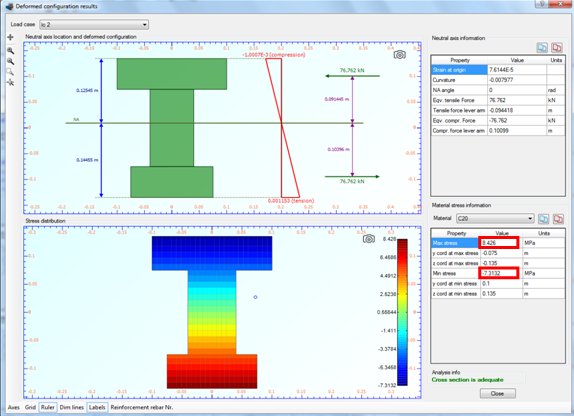
| Design for load case lc2: | adequate |
| Maximum stress: | 8.43 MPa at point (-0.075,-0.135) |
| Minimum stress: | -7.31 MPa at point (0.1,0.135) |
Results for load case lc3:
Respectively, by selecting “lc3”, appears the corresponding information for the second load case.
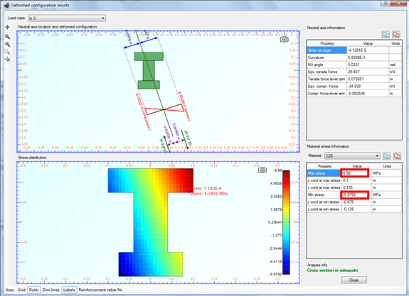
| Design for load case lc3: | adequate |
| Maximum stress: | 6.56 MPa at point (0.1,0.135) |
| Minimum stress: | -5.98 MPa at point (-0.075,-0.135) |
Watch the video of this example