Example 11: Cross sectional properties of a built-up steel section
Watch the video of this example >
Data for Cross Section Analysis & Design application
In this example, we will create a built-up steel section and calculate its properties.
Steel grade: A36 Gr.36
Solution with Cross Section Analysis & Design
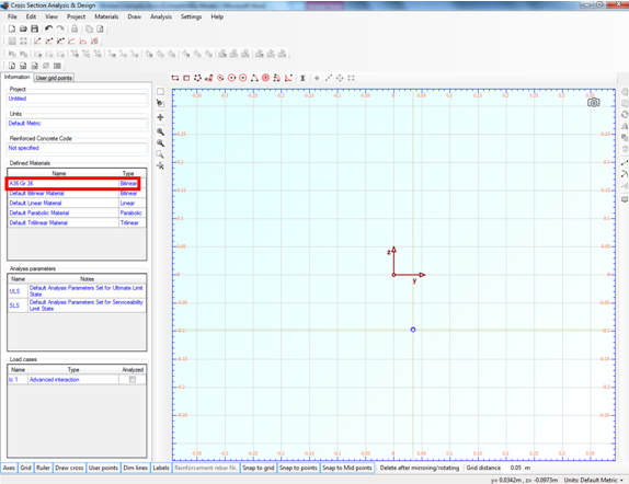
Setting Reinforced Concrete Code to None
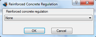
Since the cross section does not have a concrete part, we can optionally set the Reinforced Concrete code to “None”, in order to hide all data related to reinforced concrete analysis. We click on Project -> Reinforced Concrete code menu item and select “None” as below.
Definition of material properties
Next, we are going to specify the material properties.
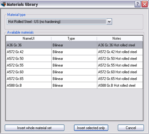
The A36 Gr.36 steel grade can be imported from the library of the program by clicking on the Materials -> Import from Library menu item. From the top list we select “Hot Rolled Steel – US (no hardening)” in order to view the materials belonging to this collection.

Then, we can select the first row (A36 Gr.36) and click on “Insert selected only” button to use this material in our project.
A36 Gr.36 steel has been imported in our project. We can view/change its properties by clicking on it from the list of the main form, as shown in the picture below.
Drawing the geometry
First we will insert a standard wide flange section from the library by clicking the Draw -> Standard Section menu item. We select the AISC13 library in the form below.
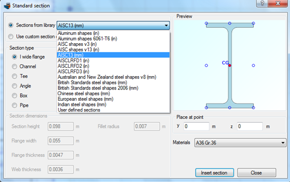
After selecting AISC13 shape family, all sections belonging to it, appear in the list below.
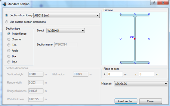
We select a W360X64 cross section.
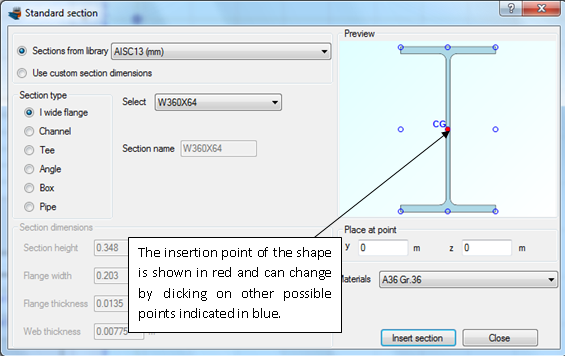
The insertion point of the shape is selected to coincide with its centroid.
We should not forget to check that the assigned material is A36 Gr.36.
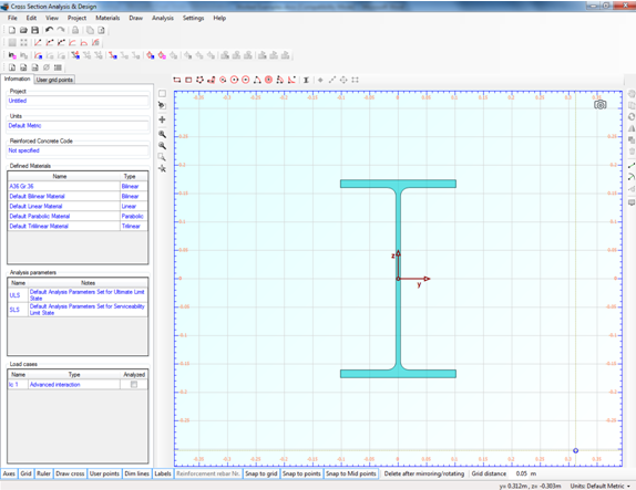
We click OK and see that the steel shape is shown in the main drawing area.
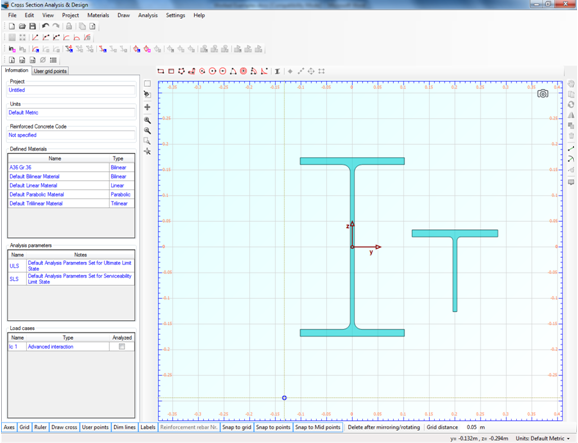
Next, we will insert a Tee section. We click again on the Draw -> Standard Section menu item and select the AISC13 library. We click on Tee section type, select WT155X26 and change the “Place at point” y value to 0.2 m.
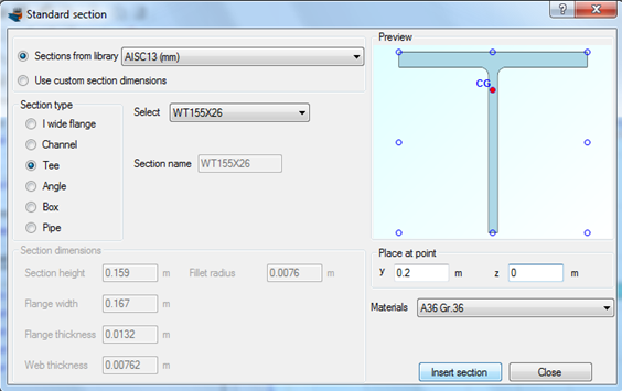
Finally we click on “Insert section” button.
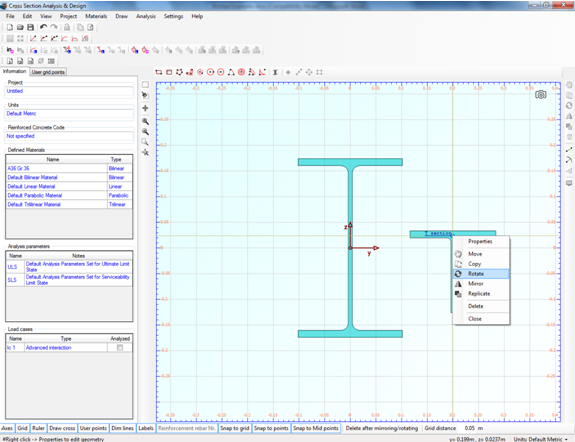
Now we need to rotate the Tee 90o clockwise. This can be done by right clicking on it and then selecting “Rotate”.
The program asks for the center point of rotation, as the status bar shows.
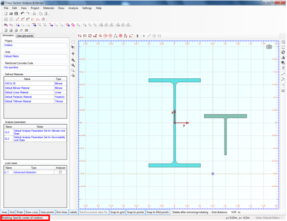
So we click on point (0.2,-0.15). Then, in order to enter the base point for rotation, we click on point (0.2,0.1). No we can move the mouse to rotate the cross section interactively.
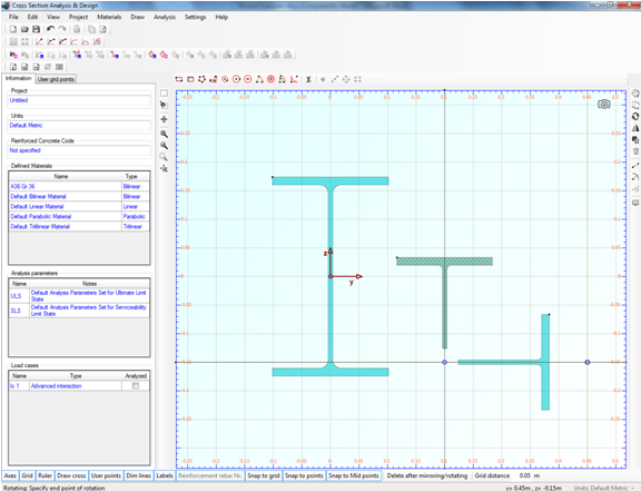
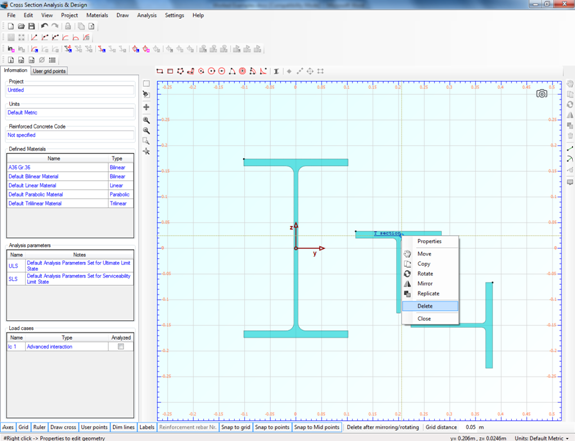
After aligning it horizontally, we can click anywhere with the mouse to fix the shape in this position. Following this action, we delete the initial section by right-clicking on it and selecting “Delete”.
Now we are about to move the Tee section next to the W section.
First, we uncheck the “Snap to grid” option, from the toolbar at the bottom of the screen.
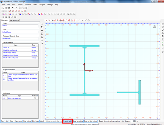
In this way, we disable the “Snap to nodes” function during editing geometry. On the other hand, the “Snap to points” option should be checked in order to enable snapping to the remaining characteristic points of the section parts except for the grid points.
In order to move the T section, we right-click on right and select “Move”.
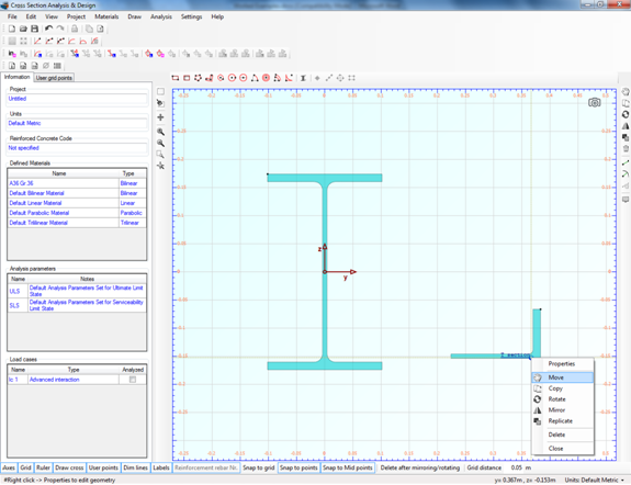
Then we click at the middle point of the Tee web and move it to the middle web point of the W section, as shown below.
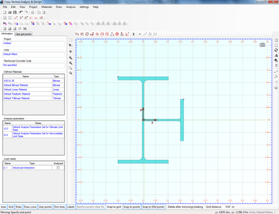
By left-clicking on that point, the T section is fixed in this position.
Next we will mirror the T section about a vertical axis. This can be accomplished by right clicking on it and choosing “Mirror”.
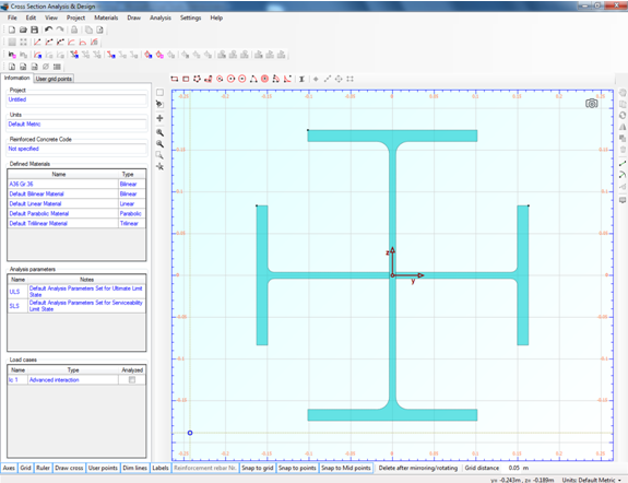
The program asks for the starting point of the mirror axis (see Status bar). We enable the snap option again by clicking on the “Snap to grid” item in the lower toolbar and successively click on points (0,-0.25) and (0,0.25).
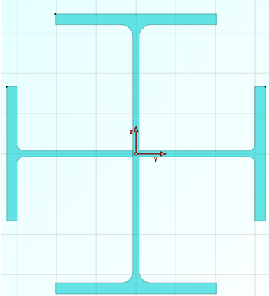
The geometry is now defined and the drawing screen should look like this.
Calculate sectional properties
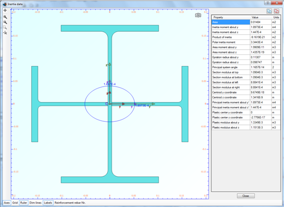
We just click Analysis -> Inertia Data -> Analyze, to have the sectional properties computed.
Results
The calculated data can be found by clicking on Analysis -> Inertia Data -> Show results menu item.