Example 8: Reinforcement design for both Ultimate and Serviceability Limit States
Watch the video of this example >
Data for Cross Section Analysis & Design application
In this example, we will perform a reinforcement design for both Ultimate and Serviceability Limit States (ULS and SLS). Such procedure is very common when designing reinforced concrete beams, since both requirements, regarding ultimate strength and cracking due to service loads should be checked.
Cross Section Analysis & Design can easily handle similar cases by modifying the default Analysis Parameters sets ULS and SLS. If more design situations should be considered, we can create new Analysis Parameters sets.
We will start from the file created in Example 7. So materials and section geometry will not change.
The additional design data are as follows:
| Concrete and Reinforcement data | Ultimate Limit State(ULS) | Serviceability Limit State (SLS) | |
| Stress/Strain distribution of concrete | Compressive part | Rectangular according to ACI 318 | Parabolic-Constant |
| Tensile part | Ignored (no tensile strength) | Yes (consider tensile resistance) | |
| Reinforcement stress limits | No limits (use full strength) | Reduce tensile strength to 220 MPa to limit crack width | |
Load cases
Moreover, the reinforcement design procedure will take place for the following loads:
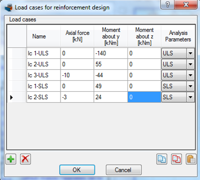
Ultimate loads (ULS)
| lc 1-ULS | N = 0 | My = -140 kNm | Mz = 0 |
| lc 2-ULS | N = 0 | My = 55 kNm | Mz = 0 |
| lc 3-ULS | N = -10 kN | My = -44 kNm | Mz = 0 |
Service loads (SLS)
| lc 1-SLS | N = 0 | My = 49 kNm | Mz = 0 |
| lc 2-SLS | N = -3 kN | My = 24 kNm | Mz = 0 |
Solution with Cross Section Analysis & Design
Opening a file from disk
First of all we click on the File menu and select Open in order to open the file we created in Example 7.
Unlock the model
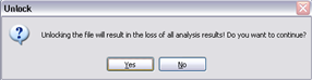
Afterwards, if the model is locked, we click on Edit -> Unlock model, in order to modify the geometry of the cross section.
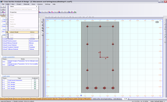
In the popup window, we choose Yes to unlock the model.
Review of Analysis Parameters
We need to modify the Analysis Parameters sets “ULS” and “SLS” to match with the design data provided above. This can be done by clicking Analysis -> Analysis Parameters.
First of all, we select “ULS” from the list at the top left corner.
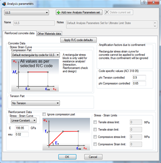
We make sure that the compressive stress strain part of concrete is set to “Default rectangular by code for ULS”. Moreover, the “No Tension” should be selected for the tensile part of concrete. The Stress/Strain limits for reinforcement are not changed as shown in picture above.
Next, we select “SLS” from the list at the top left corner.
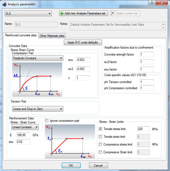
According to the given design data, we make sure that a Parabolic-Constant concrete curve has been selected. The tensile part should have the option “Linear and Drop to Zero” selected, in order to consider the tensile resistance of concrete. Finally, we have applied a tensile stress limit for reinforcement equal to 220 MPa.
We notice that the strength reduction factors are in this case equal to 1.0, since the program automatically adjusts them to be compatible to current design situation SLS. On the other hand, the default values by ACI 318 were applied for the ULS case. We click ok to close this form.
Definition of load cases
We click on the Analysis -> Reinforcement design -> Load cases menu item to enter the load cases.
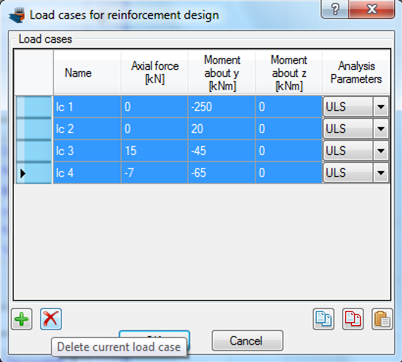
First of all, we select all the rows and click the  icon to delete them. Afterwards, we enter the load cases and assign the corresponding Analysis Parameters sets, as shown below.
Carry out the analysis
We just click Analysis -> Reinforcement design -> Analyze, to perform the analysis.
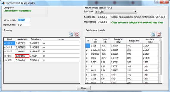
Results
The results can be obtained from the Analysis -> Reinforcement design -> Show results menu item.
Watch the video of this example