Example 5: Control of concrete cracking: Estimation of the stress at reinforcement (Serviceability Limit State)
Watch the video of this example >
Data for Cross Section Analysis & Design application
We will extend the file created in Example 2 in order to calculate the stress at each rebar under the loads defined below.
As many regulations propose, the effect of cracking can be controlled by considering a reduced reinforcement stress which is specified by other parameters, such as allowable crack width, rebar diameters, rebar spacing etc.
The concrete stress/strain curve is assumed to be linear.
Load cases
| lc 1: | N = 0 | My = -120 kNm | Mz = 0 |
| lc 2: | N = 0 | My = 37 kNm | Mz = 0 |
| lc 3: | N = 20 kN | My = -54 kNm | Mz = 0 |
Solution with Cross Section Analysis & Design
Opening a file from disk
First of all we click on the File menu and select Open in order to open the file we created in Example 2.
Unlock the model
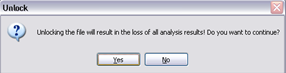
Afterwards, if the model is locked, we click on Edit -> Unlock model, in order to modify the geometry of the cross section.
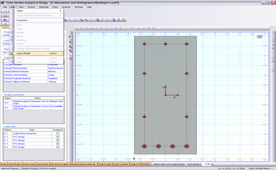
In the popup window, we choose Yes to unlock the model.
Review of Analysis Parameters
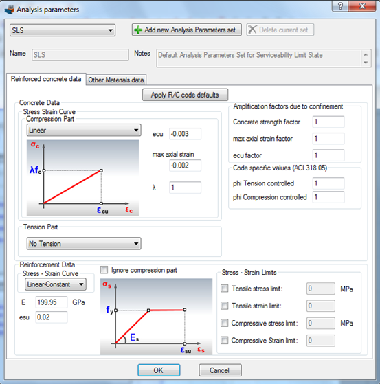
We need to specify the corresponding Analysis Parameters set by clicking Analysis -> Analysis Parameters. We will use the default “SLS” set. The concrete stress block is linear and the corresponding strain values are defined according to ACI 318. Strength reduction factors φ do not need to be changed since we are performing an analysis in Serviceability Limit State (stress calculation). The concrete tensile strength is ignored. You can override these values by modifying any of the fields of the form.
Definition of load cases
We click on the Analysis -> Deformed configuration -> Load cases menu item and next on the  button in order to insert a new load case under the name “lc 1”. Afterwards we fill the values for loads and make sure that the “SLS” Analysis Parameters set is enabled. We can create the remaining load cases lc 2 and lc 3 likewise.
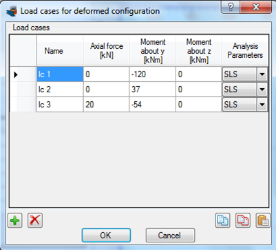
We click OK to close the form.
Carry out the analysis
We just click Analysis -> Deformed configuration -> Analyze, to perform the analysis.
Results
The results can be obtained from the Analysis -> Deformed configuration -> Show results menu item.
On this form, we choose the “lc 1” load case at the top left corner, in order to view the results related to the first defined load case.
The following data can be found on this form.
- Neutral axis location
- Strain distribution
- Equivalent force couple
- Stress contour on the cross section area
- Reinforcement forces/stresses
- Stress information per material
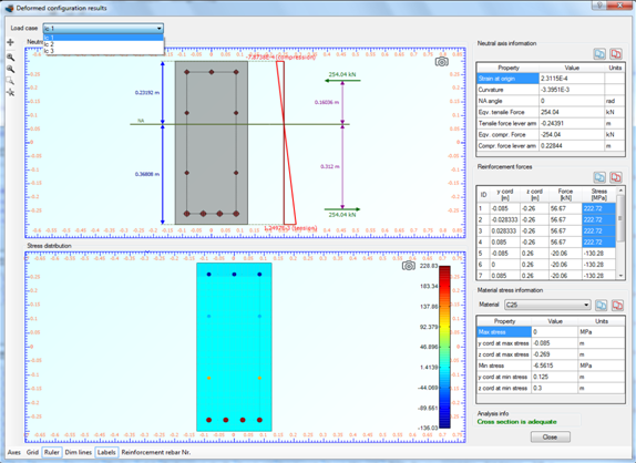
As we can see, the maximum stress values at reinfordcement are reported as expected for rebars 1 to 4 (bottom layer reinforement) and have a value of 222.72 MPa.
By the above mentioned way, we can obtain the results for the remaining load cases “lc 2” and “lc 3” by changing the selected load case item at the top left corner of the results form.