Example 1: Load case and combination definitions using 3D Frame Analysis Library
Example 1: Load case and combination definitions using 3D Frame Analysis Library
In this example, we will call the 3D Frame Library from a Visual Studio project and carry out the structural analysis of a simple beam under different load cases and one load combination. We will first provide the geometry, material properties and loads and afterwards call the corresponding routine in order to obtain the results regarding the load cases and load combination.
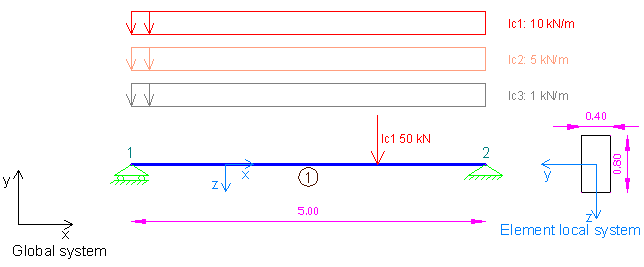
Sample beam with 3 different load cases to analyze with 3D Frame Library (Metric units)
We will first create a new C# Windows Application project from Visual Studio and follow the following steps to carry out the structural analysis according the data provided. Please notice that we could use any other .NET compatible language and take the corresponding steps. The source code of all examples can be downloaded here.
Add a reference to 3D Frame Library
A reference to Frame 3D Library can easily be added by right clicking on the application project and selecting Add --> Reference.
Providing the data to 3D Frame Library using C#
New model definition
Model Model = new Model();
Model.LicenseInfo = LicenseInfo;
Definition of materials
//Create a new material for concrete
Material matConcrete = new Material();
matConcrete.Name = "Concrete";//Material name
matConcrete.Density = 2.5;//density in mass units/m3, for example tn/m3
matConcrete.G = 11538461;//shear modulus
matConcrete.E = 30000000;//elasticity modulus
Definition of cross section
//Create a new beam section of dimensions 40cmx80xm
FrameElementSection secBeam40_80 = new FrameElementSection();
secBeam40_80.Name = "Beam40/80";//section name
secBeam40_80.A = 0.4 * 0.8;//section area
secBeam40_80.Iy = 0.4 * 0.8 * 0.8 * 0.8 / 12;//inertia moment about local y axis
secBeam40_80.Iz = 0.8 * 0.4 * 0.4 * 0.4 / 12;//inertia moment about local z axis
secBeam40_80.It = 0.0117248;//torsional constant
secBeam40_80.b = 0.40;//section width
secBeam40_80.h = 0.80;//section height
Definition of model geometry and loads
//Create node n1
Frame3D.SuperNode n1 = new Frame3D.SuperNode(1, 0, 0, 0);
n1.dof1constraint = true;//delete
n1.dof2constraint = true;//translational constraint in direction y at local system of node
n1.dof3constraint = true;//translational constraint in direction z at local system of node
n1.dof4constraint = true;//rotational constraint in direction x at local system of node
n1.dof5constraint = true;//rotational constraint in direction y at local system of node
Model.InputNodes.Add(n1);

//Create node n2
Frame3D.SuperNode n2 = new Frame3D.SuperNode(2, 5, 0, 0);
n2.dof1constraint = true;//translational constraint in direction x at local system of node
n2.dof2constraint = true;//translational constraint in direction y at local system of node
n2.dof3constraint = true;//translational constraint in direction z at local system of node
n2.dof4constraint = true;//rotational constraint in direction x at local system of node
n2.dof5constraint = true;//rotational constraint in direction y at local system of node
Model.InputNodes.Add(n2);

//Create frame element 1
//Note that the 4th argument specifies the auxiliary point that lies in the xy plane that is formed by the x and y axes in the local element system
FrameSuperElement el1 = new FrameSuperElement(1, n1, n2, new Geometry.XYZ(0, 0, 1), matConcrete, secBeam40_80, new MemberReleases(), new MemberReleases(), false, false);

LinearLoadCaseForSuperFrameElement lc1 = new LinearLoadCaseForSuperFrameElement("lc1", LoadCaseType.DEAD);
lc1.UniformLoad.UniformLoadsY.Add(new FrameSuperUniformLoad(0, 1, -10, -10, LoadDefinitionFromStartingNode.Relatively, LoadCordinateSystem.Global));
lc1.PointLoad.PointLoadsY.Add(new SuperPointLoad(3.5, -50, LoadDefinitionFromStartingNode.Absolutely, LoadCordinateSystem.Global));
el1.LinearLoadCasesList.Add(lc1);

LinearLoadCaseForSuperFrameElement lc2 = new LinearLoadCaseForSuperFrameElement("lc2", LoadCaseType.LIVE);
lc2.UniformLoad.UniformLoadsY.Add(new FrameSuperUniformLoad(0, 1, -5, -5, LoadDefinitionFromStartingNode.Relatively, LoadCordinateSystem.Global));
el1.LinearLoadCasesList.Add(lc2);

LinearLoadCaseForSuperFrameElement lc3 = new LinearLoadCaseForSuperFrameElement("lc3", LoadCaseType.LIVE);
lc3.UniformLoad.UniformLoadsY.Add(new FrameSuperUniformLoad(0, 1, -1, -1, LoadDefinitionFromStartingNode.Relatively, LoadCordinateSystem.Global));
el1.LinearLoadCasesList.Add(lc3);

Model.InputFiniteElements.Add(el1);
Call the solution method
Model.Solve();Obtain the analysis results
double[] Min, Max;//The combination results will be saved in these arrays
//Note that the definition of two arrays for minimum and maximum combination results is required
//For combination type "ADD", Min and Max values are always equal

//Reactions (All are defined in the node local system)
//Rections for load case lc1
n1.GetReactionsForLoadCase("lc1", out Min, out Max, 0);
double n1_Rty_lc1 = Max[1];
n2.GetReactionsForLoadCase("lc1", out Min, out Max, 0);
double n2_Rty_lc1 = Max[1];

//Rections for load case lc2
n1.GetReactionsForLoadCase("lc2", out Min, out Max, 0);
double n1_Rty_lc2 = Max[1];
n2.GetReactionsForLoadCase("lc2", out Min, out Max, 0);
double n2_Rty_lc2 = Max[1];

//Rections for load case lc13
n1.GetReactionsForLoadCase("lc3", out Min, out Max, 0);
double n1_Rty_lc3 = Max[1];
n2.GetReactionsForLoadCase("lc3", out Min, out Max, 0);
double n2_Rty_lc3 = Max[1];

//Node Displacements (All are defined in the node local system)
//Note that constained degrees of freedom have zero displacements
n1.GetNodalDisplacementsForLoadCase("lc1", out Min, out Max, 0);
double[] n1_Disp = Max;
n2.GetNodalDisplacementsForLoadCase("lc1", out Min, out Max, 0);
double[] n2_Disp = Max;

//Element internal forces and displacements
el1.GetInternalForcesForLoadCase(0, "lc1", out Min, out Max, 0); //Internal forces at the start of the member
double[] forces_along_member_left = Max;
el1.GetInternalForcesForLoadCase(2.5, "lc1", out Min, out Max, 0);//Internal forces at the middle of the member
double[] forces_along_member_middle = Max;
el1.GetInternalForcesForLoadCase(5, "lc1", out Min, out Max, 0);//Internal forces at the end of the member
double[] forces_along_member_right = Max;

el1.GetDisplacementsForLoadCase(0, "lc1", out Min, out Max, 0); //Internal displacements at the start of the member
double[] disps_along_member_left = Max;
el1.GetDisplacementsForLoadCase(2.5, "lc1", out Min, out Max, 0);//Internal displacements at the middle of the member
double[] disps_along_member_middle = Max;
el1.GetDisplacementsForLoadCase(5, "lc1", out Min, out Max, 0);//Internal displacements at the end of the member
double[] disps_along_member_right = Max;

//Creation of a load combination
//Note that load combinations can also be defined after analysis has been completed
//A load combination for 2.00 lc1 - 0.5 lc2 is created, as follows:
LoadCombination LCombo = new LoadCombination("combination", ComboType.ADD);
LCombo.Items.Add(new LoadCaseWithFactor("lc1", 2));
LCombo.Items.Add(new LoadCaseWithFactor("lc2", -0.5));

//All result data can be now obtained for the combination in the same way as for the load cases
//for example, get first node reactions:
n1.GetReactionsForLoadCombination(LCombo, out Min, out Max);